1988 4Runner · 98 5VZ-FE swap
Engine build
Every step in factory-manual order, with the parts each step needs. Grey chips are the manual page for that step.
Tick boxes on this page are saved in this browser only. HAVE parts start ticked.
Gasket set, both head gaskets, cam / crank / valve stem seals, rings, bearings sized from your measurements, thrust washers. FIPG 08826-00080 & 08826-00100, ThreeBond 1324, 1344/Loctite 242. Torque wrench + angle gauge, Plastigage, feelers, mic + bore gauge. SST 09960-10010 (cam scissor gear), 09201-41020 (stem seals), 09202-70020 (spring compressor). Also: SST 09816-30010 (oil pressure switch), 09817-16011 (knock sensors), 09223-15030 + 09950-70010 (rear crank seal), 09213-54015 + 09330-00021 (crank pulley bolt), 09248-55040 (valve shims), 09228-07501 (oil filter), 09301-00110 (clutch alignment). Thrust washers 2.440–2.490 mm.
Parts for this step
Tools
| Item | Status |
|---|
| Torque wrenches (in·lb and up to 250 N·m) + angle gauge, paint marker | BUY |
| Plastigage, feeler gauges, micrometer (for shims) | BUY |
| Ring expander, ring compressor, snap-ring pliers | BUY |
| Rear main seal driver, crank front seal driver (or substitutes) | BUY |
| Cam pin wrench (SST 09960-10010 or a substitute) | BUY |
| Crank pulley holder (for 250 N·m) | BUY / rent |
| Press + 1.27 mm hex key (tensioner pre-load) | access |
| Oil pressure sender deep socket | BUY / have |
| Engine stand | have / rent |
3. Short block
Oil every sliding surface; new gaskets, O-rings and seals everywhere. Freeze plugs are already in (red Loctite, done 2026-10). Have the shop confirm any oil gallery plugs it removed are back in.
Parts for this step
1. Bottom end
| Item | Qty | Spec | Status |
|---|
| NPR pistons + rings | 6 | ring code mark up, gaps staggered | HAVE-kit |
| OEM main bearings | set | 22 mm in No.1 | HAVE-kit |
| OEM rod bearings | set | | HAVE-kit |
| OEM thrust washers | 4 | grooves out | HAVE-kit |
| OEM oil pump | 1 | A 20 N·m, B 42 N·m | HAVE-kit |
| 5VZ baffle + strainer | 1 | | REUSE |
| 88 oil pan | 1 | check the strainer clears the floor | HAVE-you |
| Block auxiliary dipstick hole: drive the factory plug out from the underside with a punch (ORS), before paint and before the crank goes in | | | TO DO (before paint) |
| Oil pump's old dipstick hole (the new Kit-3002 pump has it open): press in a small freeze plug (no drilling), or tap 1/4"-18 NPT from the outside and fit a pipe plug with pipe-thread sealant (Permatex 59214, see Chemicals). Do it on the bench, before paint | 1 | | TO DO (before paint; Yotashop press-in plug on hand) |
| 88 oil pressure sender | 1 | 15 N·m, threadlocker on 2–3 threads; check the thread fits | HAVE-you |
| Crank sensor O-ring/seal from McGuckin (bought 2026-10-13). Fit check: same inside diameter and thickness as the old one; sits in the groove without twisting or bulging out; the sensor pushes in with a light, even drag. Nitrile or Viton. Smear of engine oil on install | 1 | not ◆ in the FSM | HAVE-you |
| Engine mount brackets, alternator adjusting bar, coolant drain cock | | 44 / 42 / 39 N·m | REUSE |
2. Cooling parts on the engine
| Item | Qty | Spec | Status |
|---|
| OEM water pump | 1 | 1282B in the groove, 20 N·m | HAVE-kit (timing set) |
| Thermostat (not in Kit-3002): AISIN THT019, 180 °F OE temp, RockAuto ~$15. Aisin makes Toyota's OE thermostats. Use the gasket from the kit's gasket set if the box has none | 1 | opens 80–84 °C, jiggle valve down (FSM CO-12); 20 N·m | HAVE (ordered, RockAuto) |
| Water bypass pipe | 1 | 8.5 N·m, Ultra Black in the groove | REUSE |
| Knock sensor wire: new harness, see section 3 | | | see section 3 |
| 5VZ oil cooler (coolant-to-oil plate between the block and the oil filter) | 1 | inspect for damage/clogging (LU-20); flush both sides | REUSE |
| Oil cooler union bolt: precoated, so clean the threads and recoat (Loctite 242/243) | 1 | 59 N·m (43 ft·lbf) (LU-19) | REUSE |
| ◆ Oil cooler O-ring (cooler to block) + ◆ union-bolt gasket, new | 1 + 1 | | HAVE-kit (Kit-3002 "OEM Oil Cooler Gasket Set") |
| CHECK FOR: No.1 + No.2 oil cooler coolant hoses + clamps (old rubber; easy to reach with the engine out). Toyota 15778-62030 (long S-bend) and 15777-62020 (short U-bend) | 2 | take the old ones to match the ID/length, or order by VIN | REUSE (clean; replace only if hard or cracked) |
| Heat sleeve for the oil cooler hose that passes the LH exhaust manifold (ORS) | 1 | | HAVE (DEI Heat Sheath 3/4" ID, Amazon; check the hose OD fits) |
| CHECK FOR: Throttle body water bypass hoses: stay on the throttle body, which moves onto the Magnuson (manual p.7). Replace if hard or cracked | 2 | | REUSE (clean; replace only if hard or cracked) |
3. Knock sensors (replace: buried under the intake, and the ECM needs them to pull timing under boost)
| Item | Qty | Spec | Status |
|---|
| Knock sensor wire harness 82219-34010, buy genuine. RockAuto has an aftermarket Wells 1P2619 (~$22), but this harness sits under the intake and the Magnuson, so a failure means pulling the supercharger; the ~$13 saving isn't worth it. Genuine, cheapest found: Toyota dealer Toyota ~$35; Yota1 ~$52, PartsGeek ~$54. Order with the No.3 timing cover seals to share shipping; confirm by VIN. The harness, not the sensors, is what usually fails | 1 | | HAVE (ordered, Toyota dealer) |
| Heat-reflective tape (e.g. gold or aluminized) to wrap the new knock sensor harness before the intake goes on | 1 roll | | HAVE (Thermo-Tec 14002, Amazon) |
| Knock sensor socket: 1-1/16" deep socket (same size as 27 mm), in place of SST 09817-16011 | 1 | 39 N·m | HAVE |
Pistons to rods: snap ring gap away from the cutout; heat piston to ~60 °C; front marks aligned
FSM EM-94Rings: oil ring by hand; compression rings code mark up (1R/T, 2R/T); stagger the gaps
FSM EM-94Rod bearings: claw in the groove
FSM EM-95Mains: 22 mm bearings in No.1, 20 mm in the rest; oil-hole halves go in the block
FSM EM-95Upper thrust washers at No.2, grooves out
FSM EM-95Crank in; main caps + lower thrust washers, front mark forward
FSM EM-95Main bolts: oil threads + under heads; 8 bolts in sequence, several passes, 61 N·m (45 ft·lbf) → paint front → +90° in order → paint at 90°. Replace any bolt that's broken/deformed or won't reach 61 N·m. Crank turns smoothly; recheck end play
FSM EM-96Pistons in: hoses on rod bolts, ring compressor, front mark forward
FSM EM-96Rod caps matched, front mark forward; oil threads/under nuts; alternately 25 N·m (18 ft·lbf) → paint → +90°. Replace any nut that won't reach torque, and any broken/deformed rod bolt (thread OD min 7.600 mm, section 2). Crank turns smoothly; check side clearance
FSM EM-97Rear seal retainer: prep both faces (razor blade + scraper, non-residue solvent, no oil on the faces); FIPG 08826-00080, 2–3 mm bead, within 5 min, 6 bolts 8 N·m (71 in·lbf)
FSM EM-98Oil pump: FIPG 08826-00080 2–3 mm bead (assemble within 5 min), new O-ring in block groove, drive-rotor splines on the crank's large teeth; 8 bolts + ground strap: A 20 N·m (15 ft·lbf), B 42 N·m (31 ft·lbf)
FSM LU-15Crank position sensor (7.8 N·m, 69 in·lbf, IG-12) → oil pan baffle plate
FSM LU-16Oil strainer: new gasket, 7.5 N·m
FSM LU-16Oil pan: clean flanges (don't use a solvent that attacks painted surfaces); FIPG 08826-00080 3–4 mm bead, within 5 min; 88 pan: 15 bolts + 4 nuts (FSM says 17 + 2 = post-08/2000 layout) 7.6 N·m (67 in·lbf)
FSM LU-16Oil cooler (LU-21 = reverse of removal; specs on LU-19 Removal page): new O-ring, new union-bolt gasket, union bolt 59 N·m (43 ft·lbf); connect No.1/No.2 cooler hoses
FSM LU-21Coolant drain cock 39 N·m; mount brackets 44 N·m; oil filter union 25 N·m
FSM EM-98Oil filter: clean the seat, oil the gasket, hand-tight to contact + 3/4 turn (SST 09228-07501)
FSM LU-3Oil pressure port: 1344/Loctite 242 on 2–3 threads, SST 09816-30010, 15 N·m (11 ft·lbf). Swap (not FSM): fit the 88 pulse-type oil pressure sender here
FSM EM-99Alternator adjusting bar 42 N·m
FSM EM-99Water pump: clean the groove, FIPG 08826-00100 (1282B) 2–3 mm bead in the groove, assemble within 5 min; 7 bolts 20 N·m (14 ft·lbf)
FSM CO-8Knock sensors: check no continuity terminal-to-body; install with SST 09817-16011 or a 1-1/16" (27 mm) deep socket, 39 N·m (29 ft·lbf)
FSM SF-52No.2 idler pulley bracket 38 N·m
FSM EM-99Water bypass pipe: FIPG 08826-00100 in the groove (you're using Permatex Ultra Black), fit within 5 min, 8.5 N·m
FSM EM-99Knock sensor wire (new harness 82219-34010): wrap it in heat-reflective tape, route it along the bypass pipe the way the old one ran, and plug in both knock sensors (click on each)
FSM EM-994. Heads on the bench
Parts for this step
4. Heads
| Item | Qty | Spec | Status |
|---|
| Head bolts (12-point head, 8 per head) + 16 plate washers | 16 | 34 N·m + 90° + 90° | HAVE-kit |
| Recessed head bolts | 2 | 18 N·m | REUSE |
| Semi-circular plugs | 4 | FIPG | REUSE |
| PCV valve | 1 | stock location; the Magnuson reuses it (manual p.14) | HAVE (SMP V388, RockAuto) |
Spark plug tubes (new head only): 1324, press to 49.0–49.4 mm protrusion
FSM EM-48Valves: new stem seals (intake silver, exhaust black), spring seat → spring → retainer → keepers, tap the tip
FSM EM-48Lifters + shims; each turns by hand
FSM EM-49Cam housing plugs: FIPG, cup side in, cap 16 N·m; rear plate/strap 8 N·m
FSM EM-495. Heads, cams, valve covers
⚠ UNVERIFIED (not in the FSM): set the crank at No.1 TDC (crank mark to oil pump body mark, EM-19) before the heads go on, and don't spin the crank until the belt is on.
2 new head gaskets, direction matters; heads on
FSM EM-50Head bolts oiled: 34 N·m (25 ft·lbf) in sequence → paint → +90° → +90° (paint faces rearward)
FSM EM-50Recessed head bolt (8 mm hex) 18 N·m; ground strap
FSM EM-51Exhaust cam scissor gear: spring, sub-gear, wave washer, snap ring; cam hex in a vise; gear pins to the spring ends; SST, turn the sub-gear clockwise, align the teeth, then tighten the service bolt
FSM EM-51RH cams, kept level: intake at 90° from the 2-dot mark, new seal, FIPG on No.1 cap, 16 N·m; exhaust on 2-dot marks, 16 N·m; remove the service bolt, then turn the cam with a wrench to line up the 1-dot marks
FSM EM-52LH cams, kept level: oil journals/thrust; intake at 90° from the 1-dot mark, new seal (MP grease on lip), FIPG on No.1 cap, 10 bolts 16 N·m; exhaust on the 1-dot marks, 8 bolts 16 N·m; remove the service bolt, turn the cam with a wrench to line up the 1-dot marks
FSM EM-53Valve clearance (cold): intake 0.13–0.23 mm, exhaust 0.27–0.37 mm. The FSM turns the crank (needs the belt); to stop at the covers, shim on the bench first (UNVERIFIED). FSM checks at No.1 TDC, then +240°, +240° (EM-4/5)
FSM EM-4Shims: lobe up, lifter notch perpendicular, SST 09248-55040 to hold the lifter. New shim N = T + (A − 0.18) intake, N = T + (A − 0.32) exhaust (mm). 17 sizes, 2.500–3.300 in 0.050 steps. Numbers face down. Recheck
FSM EM-54 semi-circular plugs, FIPG 08826-00080
FSM EM-55Valve covers: FIPG where shown, gasket, 8 bolts each, several passes, 6 N·m (53 in·lbf). Spark plug tube gaskets in the covers: MP grease on the lip (EM-47)
FSM EM-566. Exhaust manifolds & crossover
Parts for this step
T5. Exhaust: stock 5VZ manifolds + your own crossover
Crossover method: the YotaTech thread "Build your own 3.4 crossover pipe" (89 4Runner). Cut the 98 crossover apart, reshape it and re-weld. The manifolds and their gaskets follow section 6 (FSM EM-56/57).
| Step | Notes |
|---|
| Manifolds on with new gaskets (section 6) before the engine goes in | 40 N·m; heat insulators 8 N·m |
| Remove the crossover heat shield. Cut the factory welds, not the pipes; leave the old weld as a depth mark | Thread: cut-off wheel and die grinder |
| Mark the flex section L/R so it goes back the same way | |
| With the engine in the truck, test-fit and cut the pipe to shape. Add a short spacer pipe if the flex hits the bell-housing bolts | Thread: the flex hit the trans bolts until he added a spacer |
| Check clearance at the trans, head, frame, steering shaft and starter. Tack, re-check, weld fully | Some flanges need an ear trimmed |
| B1S1 O2 sensor: before the cat. If it hits the frame, move the bung | Thread: his O2 hit the frame |
| Downpipe, flex, cat with the B1S2 bung after the cat, muffler, hangers | 2.5" (2.25" min). Don't reuse the 3VZ downpipe or cat |
| Heat shield the firewall, harness, speedo cable and parking-brake cable | |
| Item | Qty | Spec | Status |
|---|
| 98 exhaust manifolds + heat insulators | 2 | warpage max 1.00 mm | REUSE / CHECK |
| 98 crossover pipe (to modify) | 1 | | REUSE / CHECK |
| ◆ Exhaust manifold gaskets | 2 | 40 N·m nuts | HAVE-kit gasket set (seen in kit photo) |
| ◆ Crossover gaskets | 2 | 45 N·m | HAVE-kit gasket set (seen in kit photo) |
| ◆ Crossover-to-downpipe gasket + nuts (FSM marks the nuts one-time-use), if you keep the factory flange | 1 set | 62 N·m | BUY |
| ◆ LH exhaust manifold plug gasket | 1 | | BUY |
| Manifold and crossover studs/nuts (rusty ones break) | set | | CHECK / BUY |
| Short pipe for the spacer, 2.5" tubing and bends | lot | | BUY |
| O2 bungs or flanges: the 98 O2 sensors are 2-bolt flange sensors (FSM EM-101: ◆ gasket, ◆ nuts, 20 N·m), not 18 mm threaded. Weld 98-style flanges, or use threaded bungs with threaded sensors that have the 98 connector | 2 | | CHECK / BUY |
| ◆ O2 sensor gaskets + nuts (flange type) | 2 sets | 20 N·m | BUY |
| Flex coupler (if the 98 flex is bad) | 1 | | CHECK / BUY |
| Catalytic converter (one cat) | 1 | 2.5" | BUY |
| Muffler, flanges + gaskets, hangers | lot | | BUY |
| Heat shielding | lot | | BUY |
| Welder wire, cut-off wheels, die grinder bits | | | BUY |
EM-56 step 11a: 2 NEW gaskets, exhaust manifolds, 12 nuts: 40 N·m (30 ft·lbf). Manifold warpage max 1.00 mm (SS-10).
FSM EM-56EM-56 step 11b: heat insulators, 6 nuts: 8 N·m (71 in·lbf).
FSM EM-56EM-57 step 12: 2 NEW gaskets, crossover pipe, 6 nuts: 45 N·m (33 ft·lbf). (Fit to 88 chassis/front pipe: NOT IN FSM.)
FSM EM-576b. Accessory brackets (FSM puts these before timing belt)
EM-57 step 13: PS pump bracket to RH head: 18.5 N·m (14 ft·lbf).
FSM EM-57EM-57 step 14: generator bracket to LH head: 18.5 N·m (14 ft·lbf). (Generator adjusting bar on block, 42 N·m, already done in section 3, 'Alternator adjusting bar'.)
FSM EM-57EM-57 step 15 → CH-15 (reverse of CH-6): hang generator on pivot bolt + adjusting lock nut, leave loose for belt. Final: pivot bolt 51 N·m (38 ft·lbf); lock nut 18.5 N·m (FSM prints "25 ft·lbf" on CH-6 and SS-39; 18.5 N·m = 14 ft·lbf, so the ft·lbf value is a misprint; use N·m). MAGNUSON: belt routing may change, follow Magnuson.
FSM CH-67. Timing belt & covers
Parts for this step
5. Timing belt and covers
| Item | Qty | Spec | Status |
|---|
| Timing belt | 1 | front mark forward, install cold | HAVE-kit (timing set; confirm) |
| Hydraulic tensioner + dust boot | 1 | 27 N·m, pre-load in a press, 1.27 mm pin | HAVE-kit (timing set; confirm) |
| No.1 and No.2 idlers | 2 | 35 / 40 N·m | HAVE-kit (timing set; confirm) |
| Crank bolt | 1 | 250 N·m (184 ft·lbf) | HAVE-kit |
| Cam pulleys, crank timing pulley, belt guide | | cam pulleys 110 N·m | REUSE |
| ◆ No.3 timing belt cover gaskets (EM-27): 4 grey foam rings on the back of the No.3 plate: 2 large around the cam openings, 1 small center, 1 rounded-square (lower right). Old ones found crumbling (2026-10-13), not in the kit. Scrape clean; get new from the Toyota dealer parts desk ("4 foam gaskets on back of No.3 timing belt cover"), or cut from spare kit foam / lay cured RTV rings (24 h before install). Dust seals only, not oil or coolant 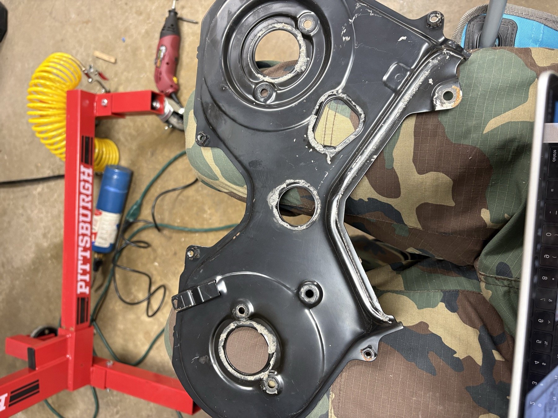 | 4 | | HAVE (plan: leftover kit foam or Ultra Black RTV rings, see TO DO below) |
| TO DO: timing cover foam. Scrape all old foam off the No.3 plate and the No.1/No.2 plastic covers; brake-clean. Lay the kit foam on the No.1/No.2 covers first (FSM EM-57 step 16), then use leftover foam for the 4 No.3 rings (2 cam openings, center hole, rounded-square hole; butt the ends tight, ~50–60 cm total). Short on foam: cured Ultra Black RTV rings (~3–5 mm tall, cure 24 h flat before installing). No.3 plate 6 bolts 9 N·m | | | TO DO (before the timing belt) |
| No.3 timing belt cover foam strips (EM-27 "Gasket", no ◆). EM-57 step 16: replace only if cracked or peeling; scrape, clean, stick new on the shaded area. Cover: 6 bolts, 9 N·m | set | | HAVE-kit gasket set (timing cover foam) |
| No.1 idler pulley bolt (★ precoated, 40 N·m) | 1 | new bolt, or clean it and use Loctite 243 | REUSE (clean, Permatex Blue) |
| Adhesive-lined heat-shrink, ~3/8" (3:1), to cover the frayed shield braid at the cam sensor connector end | 1 pack | trim the braid flush first; don't connect it to anything | HAVE-you (own heat shrink) |
| Accessory brackets (Toyota fits them before the No.3 timing cover) | 2 | 18.5 N·m | REUSE |
EM-57 step 16: check cover gaskets for cracks/peeling; if bad scrape off, clean, stick new gasket on the shaded area. 6 bolts: 9 N·m (80 in·lbf).
FSM EM-57EM-57 step 17: cam position sensor, 1 bolt: 8 N·m (71 in·lbf) [IG-10 and SS-31 say 7.8 N·m (69 in·lbf)]. Match sensor protrusion to the RH head indentation. Clamp to No.3 cover, plug connector.
FSM EM-57EM-19 step 1: crank timing pulley: key to keyway, FLANGE SIDE INWARD.
FSM EM-19EM-19 step 2: No.1 idler, plate washer + bolt (10 mm hex): 35 N·m (26 ft·lbf); check bracket moves smoothly. (EM-12 component drawing shows 40 next to it, but the text and SS-12 both say 35.) The No.1 idler bolt is a precoated part (★, EM-12): use a new bolt or clean it and apply thread-locker.
FSM EM-19EM-19 step 3: No.2 idler: 40 N·m (30 ft·lbf); check it turns smoothly. Idler/tensioner inspection EM-17/18: no seal leaks, turn smoothly. Tensioner push-rod protrusion 10.0–10.8 mm; push rod must not move when pushed hard by hand. Never hold the tensioner rod-down.
FSM EM-19EM-19 step 4: flange OUTWARD, cam knock pin into pulley groove, SST 09960-10010 (09962-01000, 09963-01000) to hold: 110 N·m (81 ft·lbf).
FSM EM-19EM-19 step 5: same as LH: flange outward, knock pin, 110 N·m (81 ft·lbf). CAUTION (EM-17): never use belt tension to hold the cam pulley while torquing its bolt.
FSM EM-19EM-19 step 6: set No.1 TDC/compression. Temporarily fit the crank pulley bolt, turn crank to align the crank timing pulley mark with the oil pump body mark. EM-20 6c: with SST, turn each cam pulley so its mark aligns with the No.3 timing belt cover mark.
FSM EM-19EM-20 step 7: engine COLD. Wipe pulleys clean (no cleaning agent). Belt front mark forward. Belt installation marks to the crank and both cam pulley marks. Route in order: LH cam → No.2 idler → RH cam → water pump → crank → No.1 idler. Don't bend, twist or turn the belt inside out, and keep oil and water off it (EM-17).
FSM EM-20EM-20 step 8: set the tensioner in a press, slowly push the rod in with 981–9,807 N (200–2,205 lbf). Align holes, insert a 1.27 mm hex key, release the press, fit the dust boot.
FSM EM-20EM-21 step 9: tensioner, 2 bolts alternately: 27 N·m (20 ft·lbf). Pull the 1.27 mm key.
FSM EM-21EM-21 step 10: check valve timing. Turn the crank CLOCKWISE to the crank pulley/oil pump marks, and check both cam pulley marks align with the No.3 cover marks. If not, remove and refit the belt. Remove the temporary crank bolt.
FSM EM-21EM-4: with the belt on, recheck valve clearance cold (bench-shimmed in section 5, 'Valve clearance'; NOT IN FSM order). Intake 0.13–0.23 mm, exhaust 0.27–0.37 mm. Recheck means covers off/on again: FIPG 08826-00080 + 6 N·m (EM-56).
FSM EM-4EM-21 step 11: timing belt guide, CUP SIDE OUTWARD.
FSM EM-21EM-21 step 12: No.1 timing cover (check/replace gasket as above), 4 bolts: 9 N·m (80 in·lbf). Starter wire bracket, 2 bolts (no torque given).
FSM EM-21EM-22 step 13: crank pulley: key to groove, slide on. SST 09213-54015 (90119-08216) + 09330-00021: 250 N·m (184 ft·lbf). MAGNUSON: if the kit changes the crank pulley, follow Magnuson.
FSM EM-22EM-22 step 14a: fan bracket, bolt + nut (no torque given).
FSM EM-22EM-22 step 14b: PS pump adjusting strut, nut (no torque given).
FSM EM-22EM-22 step 15: No.2 timing cover (check gasket), 6 bolts: 9 N·m (80 in·lbf). Clip on the 4 HT-cord clamps and the cam sensor connector. (EM-59 step 24 fits this after the air intake chamber; it's fine earlier on the stand.)
FSM EM-22EM-22 step 16: new O-ring on the dipstick guide, wet it with soapy water, push the guide into the block. Bolt to the generator bracket: 8 N·m (71 in·lbf).
FSM EM-22EM-22 step 17 (w/ A/C): A/C compressor bracket to block: 47 N·m (35 ft·lbf). MAGNUSON: some kits relocate/alter brackets, follow Magnuson.
FSM EM-228. Lower intake, fuel rail, injectors
Parts for this step
6. Lower intake, fuel rail, injectors
| Item | Qty | Spec | Status |
|---|
| Bluetop injectors ×6 (replacing the stock 5VZ 23250-62030 you have, ~240 cc): Denso 23250-46050 (2JZ-GE, 93–98 Supra NA / GS300), 312 cc @ 43.5 psi, 13.4 Ω high-impedance, air-assist tip like the 5VZ; plug-and-play on the 5VZ rail and connectors. Ordered: GB Remanufacturing 842-12135 ×6 (RockAuto, "w/ California Emissions", interchange 23209-46050 / 23250-46050). On arrival: check every stamp and ~12–14 Ω. Size them in the aftermarket ECU tune | 6 | check fit in the 5VZ rails | HAVE (ordered GB 842-12135 ×6, RockAuto) |
| ◆ Injector seals (FSM SF-19/SF-23): per injector 2 O-rings + 2 grommets (top grommet; bottom one is the "insulator") = 12 O-rings + 12 grommets. Kit has 12 O-rings + 6 insulators (kit photo, 2026-10-13), so short 6 top grommets: order from Toyota dealer (fuel injection diagram) unless the refurbished injectors came with them. Coat O-rings lightly with gasoline/spindle oil; injectors must rotate smoothly after seating | 6 grommets | check fit on the bluetops | HAVE (6 top grommets ordered, Toyota dealer; kit has the rest) |
| ECT sensor (ECM, 2-pin): AISIN THSAZ8001 (RockAuto, ~$17). Washer not included: buy a new sealing washer (Toyota dealer order, or match the old one at Advance/McGuckin); don't reuse the old one | 1 + washer | 2–3 kΩ at 20 °C | HAVE (sensor ordered, RockAuto; washer: see Buy locally) |
SF-23 step 1a: 2 NEW grommets per injector (6 bluetops). Fit of the bluetop to the stock rail, grommets and insulators: NOT IN FSM.
FSM SF-23SF-23 step 1b: light coat of spindle oil or gasoline on 2 NEW O-rings per injector. Also new insulator per injector (SF-23 illustration).
FSM SF-23SF-23 step 1c–d: twist injector CW/CCW while pushing into the delivery pipe; connector facing OUTWARD.
FSM SF-23SF-23 step 1e–g: 4 spacers on the intake manifold. Set the delivery pipes + injectors on the manifold, 4 bolts finger-tight. (FSM does this with the manifold on the head; on the stand, do it with the manifold on the bench or on the engine.)
FSM SF-23SF-23 step 1h–i: each injector must rotate smoothly. If not, an O-ring is pinched: replace it. Connectors outward.
FSM SF-23EM-57 step 19a: 2 NEW gaskets. Intake manifold + delivery pipes + injectors as one assembly: 8 bolts, 4 plate washers, 4 nuts: 18 N·m (13 ft·lbf). Manifold warpage max 0.10 mm (SS-10).
FSM EM-57EM-57 step 19b: intake manifold stay, 2 bolts: 18 N·m (13 ft·lbf).
FSM EM-57SF-23 step 3a: crossover fuel pipe, 4 NEW gaskets, 2 union bolts: 34.3 N·m (25 ft·lbf).
FSM SF-23SF-23 step 3b: 4 delivery-pipe-to-manifold bolts: 13 N·m (10 ft·lbf). Then step 2: plug in the 6 injector connectors.
FSM SF-23SF-24 step 4: fuel inlet pipe. Union + 2 NEW gaskets loosely, clamp bolt 8 N·m (71 in·lbf), then union bolt 34.3 N·m (25 ft·lbf).
FSM SF-24SF-17 step 1: NEW O-ring with a light coat of gasoline. Fit the FPR to the LH delivery pipe and check it rotates smoothly (if not, the O-ring is pinched: redo). 2 bolts: 8 N·m (71 in·lbf). Engine wire bolt.
FSM SF-17SF-17 step 2: fuel return hose to the FPR, pushed fully to the stopper and clipped. MAGNUSON: FPR vacuum/boost reference and any rising-rate FPR, follow Magnuson.
FSM SF-17SF-24 step 6: check the air-assist lines for loose connections, sharp bends and damage. MAGNUSON: the air-assist source (from the throttle body) may change with the SC, follow Magnuson.
FSM SF-24EM-58 step 21: engine wire protector, 2 clamps, 3 bolts, 2 clamps. Connect the 6 injector connectors, ECT sensor connector and ECT sender gauge connector. (98 harness kept, see swap-wiring docs.)
FSM EM-58N/A 7th injector: no cold-start/7th injector in any 5VZ-FE FSM procedure. Nothing to fit, plug or wire.
FSM SF-239. Upper intake: Magnuson (follow Magnuson manual)
Parts for this step
L. Intake / Magnuson supercharger
Your kit: Magnuson MP62, kit 01-62-34-003-BL (unit tags 60-10-62-034 / snout 60.20.62.40). Manual: references/magnuson/MP62-3.4L-Rev1-89-89-34-003.pdf (p. = manual page). Summary: research/O-magnuson-mp62.md.
| Item | Qty | Spec / part no. | Status | Source |
|---|
| Magnuson MP62 supercharger kit 01-62-34-003-BL (supercharger + manifold, belt, tensioner plate + dynamic tensioner, wire-loom + dipstick brackets, TB gasket, front-cover template, IAC check valve, hoses, plugs, bracket set) | 1 | check the box against the p.2 parts list | HAVE-user / CHECK contents | p.2 |
| Supercharger belt (replaces the alternator belt) | 1 | in the kit | HAVE-kit (Magnuson) | p.2, p.13 |
| Throttle body gasket: use the Magnuson one, not the Toyota metal one (costs ~1.5 psi boost; wrong fit = vacuum leak) | 1 | in the kit | HAVE-kit (Magnuson) | p.14 |
| Lower intake manifold gasket: reuse if good, else Toyota 17176-62040 (your gasket set has intake gaskets) | 1 | | HAVE-3002 gasket set | p.8 |
| Supercharger-to-manifold gasket = the stock surge tank (plenum) gasket (interchangeable) | 1 | | HAVE-3002 gasket set (plenum gaskets) | p.8 |
| Loctite 262 on the tensioner plate bolts (A + B); clean/tap holes A + B first | | A 25 ft·lbf, tensioner bolt 40 ft·lbf | HAVE (Loctite 271 on the chemicals list is fine) | p.10–11 |
| IAC one-way check valve spliced into the IAC hose (pre-2001 4Runner: yes). Flow toward the engine. Not the coolant hoses (those have clamps) | 1 | | HAVE-kit (Magnuson) | p.12 |
| Throttle body coolant hoses: stay on the throttle body; the TB moves onto the supercharger with them. Old rubber: replace if hard/cracked | 2 | | CHECK | p.7 |
| PCV: stock PCV valve (passenger side) + hose; kit adds a 1/2" × 34" breather hose air tube → cam cover with a red clamp at the 12 mm barb | | | HAVE-kit (Magnuson) | p.2, p.14 |
| Throttle cable bracket: the two-U bracket ("all other models"); one U is for an A/T kickdown cable you don't have. Check the 88 throttle cable fits it | 1 | | HAVE-kit / CHECK | p.14 |
| Fuel and timing: the kit has no FPR, injector or tune changes; it's built for stock injectors, stock ECU, premium 91+. Decided: 310cc bluetops. They're larger than stock, so the stock ECM needs a fueling plan (tune/piggyback). See research O | | | CHECK (fueling plan) | p.1–3 |
| Supercharger oil: the manual lists no service item | | | N/A | — |
| Intake tube, MAF housing and air filter (ORS intake, aftermarket metal cold-air kit, or custom 2.75" tubing + couplers) | 1 | — | BUY / per Magnuson manual | ORS "Intake System" |
| Throttle cable: 3VZ cable with a modified TB bracket, or a 5VZ donor cable with the firewall grommet turned around | 1 | — | CHECK / BUY | ORS "Throttle Cable" |
| Boost / vacuum gauge (monitoring) | 1 | — | OPTIONAL | recommendation |
EM-58 step 22: FSM fits the intake air connector (NEW gasket, 3 bolts + 2 nuts, 18 N·m / 13 ft·lbf), DLC1 to its bracket, ground strap, fuel return hose, FPR vacuum hose, engine wire bolt. MAGNUSON: replaced/changed, follow Magnuson install manual. Keep DLC1 (TE1/E1 needed for the timing check), the ground strap and the FPR vacuum reference.
FSM EM-58EM-59 step 23: FSM fits the air intake chamber (NEW gasket, 4 bolts + 2 nuts, 18 N·m / 13 ft·lbf). Connect TPS connector, IAC connector, 2 PCV hoses, 2 water bypass hoses, air-assist hose. MAGNUSON: replaced, follow Magnuson install manual.
FSM EM-59SF-33/35: FSM throttle body to chamber, 2 bolts + 2 nuts, 18 N·m (13 ft·lbf), NEW gasket with its protrusion UPWARD. Hoses: TPS, IAC, throttle-opener vacuum, water bypass, water hose, air assist. MAGNUSON: TB mounting changed, follow Magnuson install manual.
FSM SF-33SF-39/41: IAC valve to throttle body, NEW gasket, 4 screws (no torque in FSM). IAC resistance +B–RSO/RSC: cold 17.0–24.5 Ω, hot 21.5–28.5 Ω (SS-18).
FSM SF-39EM-59 step 25: chamber stay, 2 bolts: 40 N·m (30 ft·lbf); No.1 throttle cable clamp, 2 bolts. MAGNUSON: replaced/changed, follow Magnuson.
FSM EM-59EC-4: PCV valve check: blowing from the head-cover side passes easily, from the intake-chamber side with difficulty. Lift the inner valve and blow from the chamber side: strong resistance. Never suck through the valve. Check hoses and gaskets. MAGNUSON: PCV/breather routing changes with the SC, follow Magnuson.
FSM EC-4EM-59 steps 26–27: hoses (fuel return, fuel inlet, brake booster vacuum, EVAP, A.D.D. vacuum (4WD)). Cables: accelerator, cruise (optional); A/T throttle cable N/A (M/T, but the 98 A/T ECM is kept; ECM-side effects NOT IN FSM). MAGNUSON: vacuum/EVAP source points change, follow Magnuson.
FSM EM-5910. Ignition
Parts for this step
7. Ignition
| Item | Qty | Spec | Status |
|---|
| Spark plugs: Denso PK16TR11 double platinum (RockAuto; decision 2026-10-13, lasts longer than the stock K16TR11 and suits the waste-spark system). Same heat range; the Magnuson manual doesn't change plugs | 6 | 1.1 mm gap (check, don't regap platinum by prying on the tip) | HAVE (Denso 3289 ×6, RockAuto) |
| High-tension cords: Denso 671-6182 set (RockAuto) | 3 | max 25 kΩ | HAVE (RockAuto) |
| Ignition coils: NGK 48983 ×3 (RockAuto, black, boot included; reuse the coil bolts). Dielectric grease inside the boots | 3 | | HAVE (×3, RockAuto) |
| CHECK FOR: igniter on the donor engine. Read the part number off it (listings disagree: 89621-35010 vs 89621-35020); reuse it, new Toyota is ~$217 | 1 | | REUSE / CHECK |
IG-4: plugs ND K16TR11 / NGK BKR5EKB-11, gap 1.1 mm (0.043 in), 16 mm plug socket: 18 N·m (13 ft·lbf). (EM-3 compression section says 20 N·m (14 ft·lbf), SS-31 says 18.) Plug choice for boost: NOT IN FSM.
FSM IG-4IG-7/IG-8: 3 ignition coils on the LH head, 1 bolt each: 7.8 N·m (69 in·lbf). Refit in original order, connect the 3 coil connectors.
FSM IG-7IG-3: HT cords. Assemble holder + grommet, align the holder spline with the coil spline, push in. Tug lightly to check the lock claw is engaged. Don't pull or bend cords; disconnect at the boot. Max 25 kΩ per cord. Coil primary cold 0.67–1.05 Ω, secondary cold 9.3–16.0 kΩ (IG-5). (EM-59 step 28 does this after the intake chamber.)
FSM IG-311. Sensors
IG-12/14: crank position sensor (fitted with the oil pump, section 3, 'Crank position sensor → oil pan baffle plate'). Verify bolt 7.8 N·m (69 in·lbf). Resistance cold 1,630–2,740 Ω (SS-30).
FSM IG-12IG-10: cam position sensor (fitted in section 7): 7.8 N·m (69 in·lbf). Resistance cold 835–1,400 Ω (SS-30).
FSM IG-10SS-19: ECT sensor into the intake manifold with a NEW gasket (SF-47 drawing): 20 N·m (14 ft·lbf). ECT sender gauge connector also (EM-58). ECT resistance 20 °C 2–3 kΩ, 80 °C 0.2–0.4 kΩ (SS-18).
FSM SS-19SF-54: heated O2 sensors (B1S1 on front pipe, B1S2 on center pipe): 20 N·m (14 ft·lbf). Heater 11–16 Ω at 20 °C. Fitted with the exhaust at install (section 15).
FSM SF-54SF-27/29: MAF meter to air cleaner cap, 2 bolts: 6.9 N·m (61 in·lbf). MAGNUSON: inlet/MAF placement may change, follow Magnuson.
FSM SF-27Knock sensors already fitted (section 3, 'Knock sensors'): 39 N·m (29 ft·lbf). Listed only to confirm they're plugged in before the intake goes on.
FSM SS-1912. Cooling
Not FSM order: CO-8 connects this hose and fits the thermostat (steps 2–3) straight after the water pump, before the timing belt; here they wait until the engine is dressed. CO-8 step 2: connect the No.2 oil cooler hose (water pump already fitted, section 3, 'Water pump').
FSM CO-8Not FSM order: CO-8 step 3 fits the thermostat right after the water pump (see above). CO-12: NEW gasket on the thermostat, JIGGLE VALVE DOWN, water inlet with 3 bolts (CO-10 removal says nuts): 20 N·m (14 ft·lbf). Wire clamp (CO-9). Opens 80–84 °C (CO-11).
FSM CO-12Not FSM order: FSM fits fan, belts, A/C and PS with the timing belt, before the intake (EM-22/23); here they go on after the intake and sensors. EM-22 steps 18–19: temporarily fit the fan with fluid coupling and fan pulleys, then the No.2 fan shroud (in the vehicle, after the radiator).
FSM EM-22EM-23 step 21: after the generator belt is on, fan + fluid coupling + pulleys to the fan bracket: 5.4 N·m (48 in·lbf). (SS-23: fan to fluid coupling 7.4 N·m (65 in·lbf), a different joint.)
FSM EM-2313. Accessories: alternator, PS pump, A/C, starter
Parts for this step
J. Charging and starting
| Item | Qty | Spec / part no. | Status | Source |
|---|
| Starter: either the 5VZ starter with the lower hole drilled 7/16" to fit the 3VZ bell-housing, or the 3VZ starter | 1 | 1.4 kW or 1.8 kW type. Rebuilt or new recommended | CHECK / BUY | ORS "Engine Install"; SS-34 |
| Alternator (5VZ) | 1 | 12 V, 60 A rated in RM580U SS-38. Regulator 13.7–14.7 V; brushes min 1.5 mm exposed. Rebuilt or new recommended | CHECK / BUY | SS-38 |
| Lower alternator bracket: cut off the adjuster for steering-shaft clearance; may need a shorter belt | 1 | — | CHECK (modify) | ORS "Engine Preparation" |
| Drive belt: generator | 1 | New belt 160 ± 20 lbf | BUY: look up length | SS-38; EM-11 |
| PS pump: SKP SK215229 (new; w/ pulley, reservoir, cap) | 1 | $98.79 RockAuto 2026-10-28. Move the PS pressure switch (P22) over from the donor pump. Bleed per SR (binder §15) | BUY: RockAuto | RockAuto 1998 4Runner 3.4L |
| Drive belt: PS pump | 1 | — | BUY: look up | EM-11 |
| Drive belt: A/C compressor (5VZ comp, or 3VZ comp with the 5VZ clutch per ORS) | 1 | — | BUY: look up | EM-11; ORS "A/C System" |
| Supercharger belt / idler | 1 | Per Magnuson manual | BUY | per Magnuson manual |
| Fusible link / main alt fuse (88 AM1 60/80 A, or ORS 80–100 A fuse/link with 8–6 ga) | 1 | — | CHECK / BUY | Wiring table; ORS "Alternator Wiring" |
| Battery | 1 | 12.7–12.9 V rest | CHECK | SS-38 |
| Battery cables: reuse 88 or donor 98 battery harness. ORS-EC046 battery harness and ORS-EC047 fuse-box extension only if relocating the battery LH | set | — | REUSE / OPTIONAL | ORS "Battery Cables/Connections" |
| Battery relocation tray ORS-EC030/EC040 (only if moving the battery for intake / supercharger routing) | 1 | — | OPTIONAL | ORS "Battery Relocation Tray" |
Not FSM order: FSM fits the belts and accessories with the timing belt, before the intake (EM-22/23). EM-23 step 20 → CH-3: generator belt. Tension with gauge BTG-20 (95506-00020) / Borroughs BT-33-73F: new 160 ± 20 lbf, used 100 ± 20 lbf. Check it sits in the rib grooves (feel at the crank pulley). After 5 min running, recheck. Torque the pivot and lock nut (see 6b). MAGNUSON: belt length/routing per Magnuson.
FSM CH-3EM-23 step 22: A/C compressor to bracket, 4 bolts: 25 N·m (18 ft·lbf) (AC-51 misprints "18 in·lbf"). Connect the compressor connector. Hoses at install: NEW O-rings lubed with compressor oil, 2 bolts 10 N·m; uncap only right before connecting (AC-51).
FSM EM-23AC-18: A/C belt. Idle pulley lock nut snug 2.5 N·m (22 in·lbf), fit the belt, set tension with the adjusting bolt: new 160 ± 25 lbf, used 100 ± 25 lbf. Lock nut 39 N·m (29 ft·lbf). PS belt goes on after. MAGNUSON: belt drive changed, follow Magnuson.
FSM AC-18SR-47 step 1 / EM-23 step 23a: PS pump, bolt A + nut B finger-tight.
FSM SR-47SR-47 step 2: belt on, tension with bolt C (SR-3: new 135–180 lbf, used 85–120 lbf). Then bolt A + nut B: 43 N·m (SR-47 says 32 ft·lbf, EM-23 and SS-12 say 31 ft·lbf).
FSM SR-47SR-47 step 3: pressure feed tube, NEW gasket, union bolt: 46 N·m (34 ft·lbf), with the tube stopper touching the pump body. EM-23 23d: tube clamp bolt.
FSM SR-47SR-47 step 4: PS oil pressure switch on the feed tube: 21 N·m (15 ft·lbf). Keep oil off the switch, and replace it if dropped (SR-40). Return hose (step 5). PS air hoses to the intake chamber and resonator (EM-23 23e): MAGNUSON: changed, follow Magnuson.
FSM SR-4714. Flywheel & clutch
Parts for this step
8. Flywheel and clutch
| Item | Qty | Spec | Status |
|---|
| Flywheel LFW199 | 1 | runout max 0.1 mm | HAVE-you (confirm) |
| 3.4 pilot bearing | 1 | | HAVE-clutch kit |
| 3.4 clutch disc (springs toward the flywheel) | 1 | | HAVE-clutch kit |
| 3.4 pressure plate | 1 | 19 N·m | HAVE-clutch kit |
| Alignment tool | 1 | | HAVE-clutch kit |
| 3.0 release bearing | 1 | goes in the bell-housing | HAVE-clutch kit |
Not FSM order: FSM removes the stand right after the timing belt (EM-100 step 27); here the engine is dressed on the stand first. EM-100 step 27: support the engine on the hoist and remove the engine stand.
FSM EM-100EM-100 step 28: rear end plate to block: 7.5 N·m (66 in·lbf). (Rear end plate to trans 18 N·m, at trans install, MT-5.)
FSM EM-100EM-100 step 30 (M/T, refers to step 29). LFW199 flywheel with bolts 90105-10138. Adhesive 08833-00070 / ThreeBond 1324 (or equivalent) on 2–3 threads at the bolt end. 8 bolts, evenly in several passes in the sequence shown: 85 N·m (63 ft·lbf). Bolt PN 90105-10138 and LFW199 fitment: NOT IN FSM (spec is for the stock flywheel).
FSM EM-100CL-17 step 3: flywheel runout max 0.1 mm (0.004 in).
FSM CL-17CL-17 step 4: pilot bearing must turn without sticking (sealed; no cleaning or lube). Replace: SST 09303-35011 to pull, 09304-30012 + hammer to fit (CL-18). CL-18 5d: "install 2 new bolts", 5VZ 85 N·m (63 ft·lbf); these are flywheel bolts (FSM removes 2 opposite bolts for access).
FSM CL-17CL-17 steps 1–2 (new 3.4 kit, still check): disc rivet depth min 0.3 mm, disc runout max 0.8 mm. Cover diaphragm-spring finger wear max depth 0.6 mm, max width 5.0 mm (CL-18).
FSM CL-17CL-19 step 1a: align the disc with SST 09301-00110 (clutch alignment tool). Disc "Flywheel Side" mark toward the flywheel (CL-19 illustration).
FSM CL-19CL-19 1b–c: align cover/flywheel matchmarks (applies to a reused cover). 6 cover bolts in the order shown, No.1 and No.2 snugged first: 19 N·m (14 ft·lbf).
FSM CL-19CL-19 step 2: diaphragm spring tip non-alignment max 0.5 mm. Adjust with SST 09333-00013.
FSM CL-19CL-19 step 3: Toyota Genuine Release Hub Grease (or equivalent) on the fork/hub contact, fork/push-rod contact and fork pivot. Release fork support (pivot) 5VZ: 47 N·m (35 ft·lbf) (SS-41, CL-15).
FSM CL-19CL-19 step 4: clutch spline grease on the input-shaft/disc splines. Step 5: boot, release bearing and fork onto the transmission. Release bearing: turns freely under axial load, sealed (CL-18).
FSM CL-1915. Engine install & first start
Parts for this step
T6. Cooling, accessories and install parts
Radiator, shroud, mounts and throttle cable: see "Parts to keep from the 3VZ" (T1); buy new only if yours are bad. Clutch fork parts are in section 14, Magnuson intake parts in section 9.
| Item | Qty | Spec | Status |
|---|
| New 5VZ starter (Denso or a parts-store reman with a lifetime warranty; ~$70–160 aftermarket). Order by the number on your old starter and match its kW (1.4 or 1.8). Drill the lower mounting hole to 7/16" so it bolts to the 3VZ R150 bell-housing (ORS) | 1 | 39 N·m | HAVE (Denso 280-0167 reman, RockAuto; return the old starter for the $34 core) |
| Old 5VZ starter: keep as a spare, or core charge if the new one is a reman | 1 | | CORE (return to RockAuto) |
| 5VZ fan + fan clutch (ORS: the 3.4 fan is preferred). Check the clutch for wobble or oil leaks, and the blades for cracks | 1 each | | HAVE-you |
| 91–95 3VZ 4×4 engine block brackets, LH + RH (cast steel; used: eBay / junkyard / car-part.com). Check each has the 5VZ's 3-hole pattern (1 top, 2 bottom) before buying. Bolt to the 5VZ block; may need one A/C bracket boss ground flush (ORS); drive out the small coolant drain pipe below the block drain plug if it hits | 1 pair | | BUY |
| 91–95 3VZ 4×4 engine mounts (insulators): Ordered: Westar EM8164 ×2 (RockAuto, listed Front 4WD for 1991 Pickup 3.0L) | 1 kit | | HAVE (Westar EM8164 ×2, RockAuto) |
| 88 frame brackets (welded to the frame): stay. Clean, check welds for cracks and threads; reuse the 88 mount-to-frame hardware (38 N·m) | 2 | | REUSE |
| Radiator cap (88 radiator: 13 psi, e.g. Gates 31333; dropped from the RockAuto order, buy locally) | 1 | 74–103 kPa | HAVE-you |
| Upper and lower radiator hoses (lower: ORS hose with the 5VZ thermostat housing, or a 3VZ housing + hose) | 2 | | BUY |
| Heater hoses, throttle body water hoses, hose clamps | set | | BUY |
| A/C bracket: grind one boss flush for the 91–95 brackets | | | CHECK |
| Alternator (5VZ): lower bracket adjuster cut for steering shaft clearance | 1 | 13.7–14.7 V | CHECK |
| CS144 140 A alternator swap (decision 2026-10-13; replaces the 160 A Quality Power plan): GM CS144, 140 A, new (ordered: WAI Global 8219N, new, $127.79 RockAuto; ACDelco Gold 335-1047 is the same type, or another CS144 from a 94–96 C/K 2500/3500 5.7/7.4, Suburban/Tahoe, 96–99 Express). Plus the TEQ/Xtrusion CS144 harness for the 96–02 4Runner 5VZ (~$20, Toyota 3-pin IG–S–L to GM plug, no splicing). Expect: shim the top ear, possibly make a lower bracket, space the pulley to line up with the Magnuson 4-rib belt (K040620 may change length: measure at mock-up), check steering-shaft clearance in the 88. Charge wire 4 AWG min (2 AWG with the Big 3) + fuse | 1 | 13.7–14.7 V | HAVE (WAI Global 8219N + TEQ harness) |
| Drive belts: supercharger (also drives the alternator), PS, A/C | 3 | | HAVE 3 (SC K040620, PS K040420, A/C 4PK870, RockAuto); re-measure the SC belt after the CS144 mock-up |
| PS hoses: 3VZ pressure hose; return hose 3/8" + clamps | | | REUSE / BUY |
| ◆ PS banjo copper washers (crush gaskets for the pressure-hose union bolt), new | 2 (+ spares) | one each side of the banjo; union bolt 46 N·m (34 ft·lbf), tube stopper touching the pump body first (98 FSM, PS vane pump installation) | BUY |
| Clutch slave cylinder (new or rebuilt); master cylinder check | 1 | | BUY / CHECK |
| Heated O2 sensors B1S1 + B1S2 (98 type) | 2 | heater 11–16 Ω | BUY |
| PCV hose, vacuum hose, brake booster hose | | | BUY |
| 5VZ pulley + clutch plate moved onto the 88 compressor on the truck, shim kept (ORS / swap thread); refrigerant stays sealed | | | CHECK |
| Battery | 1 | 12.7–12.9 V at rest | CHECK |
T7. Fluids for first start
| Item | Qty | Spec | Status |
|---|
| Engine oil 5W-30 for first start, break-in and winter (FSM "preferred") | 2 fills (~12 qt) | 5.5 qt with filter (dry fill 6.2 qt) | BUY |
| Engine oil 10W-30: saving it for next summer | | | HAVE-you |
| Spare Carquest 85348 filter for the early break-in change | 1 | | BUY |
| Coolant (ethylene glycol, 50–70%) + distilled water | ~3 gal | | BUY |
| R150 gear oil 75W-90 GL-4/GL-5 | ~2.5 qt | | BUY |
| PS fluid (Dexron II/III) | 1 qt | | BUY |
| Brake fluid DOT 3 (clutch bleed) | 1 pt | | BUY |
| Fresh fuel | | | |
EM-75 step 1a–d: hoist chain on the engine hangers, lower, keep level, align RH/LH mounts with the body mounts, 4 bolts/nuts finger-tight. FSM 4WD installs the engine ALONE and the trans after (step 14). 88-chassis mount adaptation: NOT IN FSM.
FSM EM-75EM-75 1e–g: remove the hoist, then engine hanger No.2 (2 bolts; 40 N·m when refitted, SS-12). A/C compressor wire bolt.
FSM EM-75EM-75 step 2: mount insulators to body mounts, 4 bolts/nuts: 38 N·m (28 ft·lbf).
FSM EM-75Not FSM order: trans goes in before wiring and radiator (FSM EM-76 step 14 fits it after wiring, hoses, radiator, fluids and under cover). CL-20 step 6 / EM-76 step 14 → R150F MT-7 = reverse of MT-4…6. FSM conflict: CL-20 points R150F at MT-3; the installation page is MT-7 (reverse of removal, MT-4).
FSM CL-20MT-5/6: trans (with transfer) to engine, 6 bolts: 72 N·m (53 ft·lbf). Reconnect the harness. (Transfer to trans 8 bolts 24 N·m, MP grease on the transfer adaptor seal lip, MT-6.)
FSM MT-5MT-5 step 14 / ST-3: starter, 2 bolts: 39 N·m (29 ft·lbf). Starter wire nut 8.8 N·m (78 in·lbf per SS-35; ST-3 prints 70 in·lbf). Connector. Starter fit to R150 bellhousing: NOT IN FSM.
FSM MT-5MT-5: engine rear mounting to trans 4 bolts 65 N·m (48 ft·lbf). Crossmember to frame 4 bolts/nuts 65 N·m. Rear mounting to crossmember 4 bolts 18 N·m (13 ft·lbf). Rear end plate to trans 4 bolts 18 N·m. FSM conflict: SS-12 gives 58 N·m (43 ft·lbf) for frame crossmember x engine rear mounting bracket; MT-5 says 65 N·m for the crossmember bolts. Confirm on the part.
FSM MT-5MT-5 / EM-101: front pipe to crossover, NEW gaskets, 3 nuts: 62 N·m (46 ft·lbf). Bracket 3 bolts 44 N·m (33 ft·lbf). O2 sensor 2 nuts + NEW gasket. Front-to-center pipe 2 bolts + NEW gasket 48 N·m (35 ft·lbf). Support bracket 2 bolts 19 N·m (14 ft·lbf). 88 exhaust adaptation: NOT IN FSM.
FSM MT-5MT-4: clutch release cylinder and line to the clutch housing, 4 bolts: 12 N·m (9 ft·lbf). Bleed the clutch after (CL-14). Line union 15 N·m, bleeder 11 N·m (SS-41). FSM conflict: CL-11 and SS-41 give 13 N·m (9 ft·lbf) for the 2 release-cylinder bolts; MT-4's 12 N·m covers the 4 cylinder + line bolts. Use 13 on the cylinder.
FSM MT-4MT-4: MP grease on the shift-lever tip, refit the lever (press cap down, turn CW). Transfer shift lever (TR-5). Propeller shafts (PR-8). L4, 4WD position, VSS and back-up switch connectors.
FSM MT-4MT-4: trans oil API GL-4 or GL-5, SAE 75W-90, 2.2 L (2.3 US qt), level 0–5 mm below the filler hole. Plug 37 N·m (27 ft·lbf).
FSM MT-4EM-75 step 3: engine wire through the cowl, 2 nuts, bolt + bracket, clamp. Ground strap, igniter connector, VSV (EVAP), vapor pressure sensor + VSV connectors. 4 ECM connectors, 2 cassette connectors, ECM 2 bolts. 88-chassis harness/ECM location: per swap-wiring docs (NOT IN FSM).
FSM EM-75EM-75/76 steps 4–5: generator wire (CH-15). Starter wire 3 clamps + connector, battery + cable (2 nuts), ground strap bolt, wire to Relay Block No.2.
FSM EM-76EM-76 steps 6–8: hoses (fuel return, fuel inlet, brake booster vacuum, EVAP, A.D.D. vacuum; 88 equivalents NOT IN FSM), heater hoses, fan with fluid coupling (EM-19). MAGNUSON: booster/EVAP vacuum source, follow Magnuson.
FSM EM-76EM-76 step 10 → CO-23 (reverse of CO-18): radiator, 4 bolts 12 N·m (8.7 ft·lbf), support tabs through the service holes. Lower/upper hoses, reservoir hose, No.2 fan shroud, grille (7 clips). A/T cooler hoses N/A (M/T). Air cleaner (EM-76 step 9): MAGNUSON: inlet changed.
FSM CO-18LU-3/4: drain plug, NEW gasket, 39 N·m (29 ft·lbf). Oil filter: oil the gasket, hand-tight to contact + 3/4 turn (SST 09228-07501). DRY FILL 5.9 L (6.2 US qt). API SH/SJ Energy-Conserving or ILSAC, 5W-30 preferred. Boost oil choice: NOT IN FSM.
FSM LU-3CO-2: ethylene-glycol coolant, >50% and ≤70%, mixed with demineralized or distilled water. NO alcohol-type coolant. 8.0 L w/o rear heater (9.0 L with). Drain cock 39 N·m (section 3, 'Coolant drain cock').
FSM CO-2SR-4: PS fill ATF DEXRON II or III, 0.8 L total (PP-105). Bleed: front up, engine off, lock-to-lock several times. Lower, idle a few minutes, hold full lock 2–3 s each way, repeat. Check for foaming, recheck level.
FSM SR-4CL-14: bleed the clutch hydraulics. Pedal height 175–185 mm from floor panel, freeplay 5–15 mm, push-rod play 1–5 mm, release point ≥25 mm from full-stroke end (SS-40, 98 pedal).
FSM CL-14SF-5: prime the pump (hand-held tester active test, or jumper battery to the pump connector) and confirm pressure. Check for fuel leaks (SF-24 step 9) BEFORE cranking.
FSM SF-5SF-6/7: fuel pressure (gauge SST 09268-45012 at the delivery pipe union) 265–304 kPa (38–44 psi). At idle with the FPR vacuum hose connected 226–265 kPa (33–38 psi). At idle with the FPR vacuum hose off and plugged: 265–304 kPa. Holds ≥147 kPa (21 psi) for 5 min after shutdown. After the test, refit the fuel pipe with 4 NEW gaskets, 34.3 N·m (25 ft·lbf), and leak-check. MAGNUSON: boost fuel pressure, follow Magnuson.
FSM SF-6EM-59 step 33: start and check for fuel, oil, coolant and exhaust leaks. Bleed coolant, top the reservoir to FULL (CO-2).
FSM EM-59LU-1: warm engine. Remove the switch with SST 09816-30010 and fit a mechanical gauge: idle ≥29 kPa (4.3 psi), 3,000 rpm 245–520 kPa (36–75 psi). Refit the switch/sender: 08833-00080 / TB1344 / Loctite 242 on 2–3 threads, 15 N·m (11 ft·lbf) (LU-2). Swap: the 88 pulse-type oil pressure sender goes here (section 3, 'Oil pressure port' step).
FSM LU-1EM-9: warm up, scan tool on DLC3, timing light. Idle 700 ± 50 rpm (neutral, A/C off) after a 5 s blip to 1,000 rpm. Jumper TE1–E1 at DLC1 (SST 09843-18020): 8–12° BTDC. Remove the jumper: mark moves within 3–19° BTDC. 88 chassis has no DLC3; DLC1 must come with the 98 harness (NOT IN FSM).
FSM EM-9EM-10: idle check conditions: hot engine, air cleaner on, intake and vacuum lines connected, accessories off, SFI connectors plugged, timing checked, neutral, A/C off. Idle 700 ± 50 rpm. If off, check the IAC and air intake (MAGNUSON intake leaks).
FSM EM-10CH-4: no load ≤10 A, 13.7–14.7 V at 25 °C. With load (high beams, blower HI, 2,000 rpm) ≥30 A. Recheck all belt tensions after 5 min running (CH-3, SR-3, AC-16).
FSM CH-4AC-51 steps 7–9: evacuate, charge 650 ± 50 g (22.9 oz) (98 system; 88 system charge NOT IN 98 FSM), leak check with a detector.
FSM AC-51EM-2 (optional baseline after break-in): hot engine, WOT, ≥250 rpm cranking. STD ≥1,200 kPa (174 psi), min 1,000 kPa (145 psi), max 100 kPa (15 psi) spread between cylinders. Plugs back 20 N·m per EM-3 (18 per IG-4).
FSM EM-2EM-76 steps 13–17: under cover, hood, road test (noise, shock, slippage, shifting), recheck coolant and oil.
FSM EM-76